 |
|||
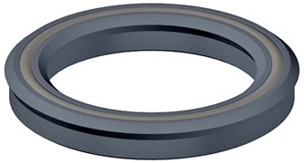
Loaded U-Cup Description Loaded U-cups are excellent seals for low-pressure rod and piston applications. With loaded U-cups, as the system pressure increases, so does the force on the loading lips. This automatically compensates for the higher pressure, while still maintaining a positive seal. A variety of styles, materials and sizes are available to suit specific requirements. | |||||||||||||||||||||||||||||||||||||||||||||||||
| Profiles | 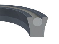 | Square with a Straight Lip The standard O-ring loaded U-cup profile is square in cross section and it is suitable for both rod and piston applications. The standard design can be used to replace existing hydraulic packing and O-Rings without changing gland design. | |||||||||||||||||||||||||||||||||||||||||||||||
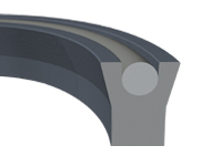 | Deep with a Straight Lip The deep O-ring loaded U-cup design is a modified version of the standard square U-cup shape. This design has approximately 1-1/2 times the axial depth of the square profile, which greatly adds to the stability of the design in higher-pressure applications. Generally, a gland would have to be modified for this seals when replacing O-rings. The deep O-ring loaded U-cup is an ideal design for replacing V or W packing, or braided rope packing. | ||||||||||||||||||||||||||||||||||||||||||||||||
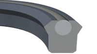
 | Deep with a Beveled Lip The type B O-ring loaded U-cup is similar in design to the deep U-cup with a straight lip, except it features a back beveled sealing lip. The beveled lip is designed to provide additional film breaking ability and increased squeeze on the sealing surface. The back bevel on the lip aligns the seal interface near the centerline of the O-Ring energizer. This provides an increased sealing force, which adds to the low pressure sealing capability while also increasing the high pressure sealing ability. The added length also provides stability to the seal. | ||||||||||||||||||||||||||||||||||||||||||||||||
 | Square with a Beveled Lip The Square beveled design provides you with the additional sealing ability of the back bevel lip design, while still being able to replace o-rings without changing the groove. | ||||||||||||||||||||||||||||||||||||||||||||||||
Part Numbers 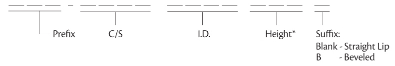
Example: LUC 1250 1062 250 B - Urethane U-cup with a straight lip and Nitrile O-ring- 0.125 C/Sm 1.062 Nominal I.D., 0.250 Height (nominal depth) Go to loaded U-cup size charts. | |||||||||||||||||||||||||||||||||||||||||||||||||
Design Considerations Surface Finish Surface finishes that are too high or low can reduce seal life. The chart below provides a general guideline on surface finish. However, RMS surface finish alone does not ensure good seal performance. With some applications contacting Hi-Tech Seals for additional recommendations is suggested.
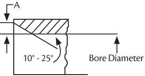
Chamfers Chamfers are used as a guide to aid seal installation. The A dimension shown below will allow the O-ring loaded U-cup to enter a cylinder bore and should be the minimum width designed.
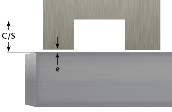
Cross Section vs. Diameter If the seals cross-section it too large in relation to the seals diameter installation can become increasingly difficult. The guidelines below are based on urethane.
Guideline is based on urethane Pressure Resistance Several variables affect a u-cups ability to resist pressure. These factors include material, heat, and extrusions gap. Extrusion Gap
|
|||||||||||||||||||||||||||||||||||||||||||||||||