O-Ring Cross-Section
The I.D. and O.D. of an O-ring gland is primarily influenced by the diameter of the mating surface of the rod or piston and bore. Although the cross-section of the O-ring may seem arbitrary, there are some distinct advantages to either a larger or smaller cross-section O-ring.
Smaller Cross-Sections Advantages
- More compact
- Lighter weight
- Less expensive; especially for higher cost elastomers like fluorocarbon (FKM) or fluorosilicone (FVMQ, FMQ)
- Less machining required for machined grooves since grooves are smaller
- Increased resistance to explosive decompression
Larger Cross-Sections Advantages
- Less prone to compression set
- Less volume swell in liquid on a percentage basis
- Allows for larger tolerance while still maintaining acceptable compression squeeze and compression ratio over full stack-up range
- Less prone to leakage due to contamination; dirt, lint, scratches, etc.
O-Ring Gland Types
O-rings are primarily used to prevent the loss of a fluid or gas. However, O-rings can be used as dust seals, drive belts, or on rotating shafts. Most O-ring seals can be classified into one of the three arrangements or configurations below.
Piston Configuration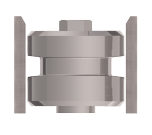 | Rod Configuration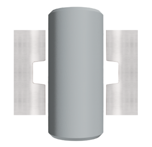 | Face Type Configuration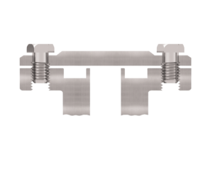 |
O-Ring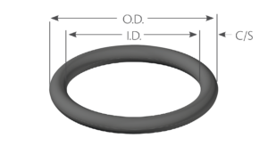 | Piston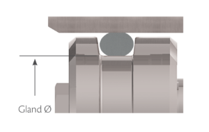 | Rod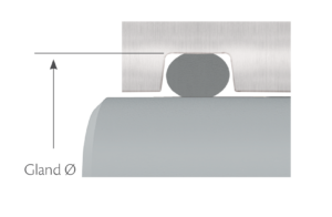 |
I.D. = Inner Diameter
O.D. = Outer Diameter
I.D. Stretch & O.D. Interference
| For hydraulic and pneumatic piston sealing applications
| For hydraulic and pneumatic rod sealing applications
| |
| The O-ring’s I.D. should be stretched between 2% and 5% for dynamic applications and 2% and 8% for static applications. For O-rings with an I.D. smaller than 20 mm, this is not always possible which can result in a wider range of stretch. To minimize this range and the maximum stretch, it is necessary to minimize the tolerance of the piston gland diameter and have a less stringent requirement for the minimum O-ring stretch. In dynamic applications, it is important to keep the maximum stretch to 5% or less to avoid detrimental effects on sealing performance. | The O-ring’s O.D. should be equal to or larger than the rod gland diameter to give interference on the O-ring O.D. The O-ring O.D. should not exceed 3% of the rod gland diameter for O-rings with an I.D. greater than 250 mm, or 5% for O-rings with an I.D. smaller than 250 mm. For O-rings with an I.D. smaller than 20 mm, this is not always possible due to tolerance issues, which can result in a greater O-ring O.D. interference. |
Reduction in Cross-Section
If the I.D. of the O-ring is stretched, the cross-section of the O-ring will decrease. The following table gives the O-ring cross-sections that result from various percentages of I.D. stretch.
Compression
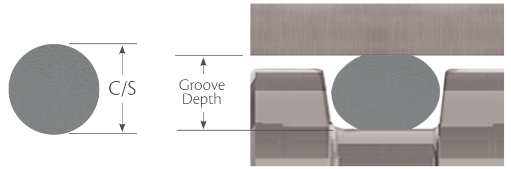
Compression squeeze is the difference between the original O-ring cross-section and the final O-ring cross-section once installed.
Compression Squeeze = C/S – Groove Depth
This can usually be expressed as a percentage:
O-ring C/S Squeeze (%) = (Compression Squeeze / C/S) x 100
Gland Fill
The gland fill is the percentage of the gland that is occupied by the O-ring. It is calculated by dividing the cross-sectional area (CSA) of the O-ring by the cross-sectional area of the gland.
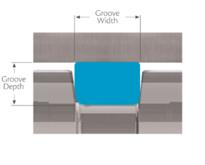
It is important to consider the groove fill or occupancy of the installed O-ring to avoid detrimental effects on radial sealing performance. The groove fill of the installed O-ring should not exceed 85% to allow for possible O-ring thermal expansion, volume swell due to fluid exposure and effects of tolerances.
Volume change is the increase or decrease of the volume of an elastomer after it has been in contact with a fluid, measured in percent (%). For static O-ring applications volume swell up to 30% can usually be tolerated. For dynamic applications, 10 or 15% swell is a reasonable maximum unless special provisions are made in the gland design itself. This is a general rule and there may occasionally be exceptions.
It is also important to note there are significant differences in the coefficients of thermal expansion between the O-ring material and the groove materials. Elastomers can have coefficients of thermal expansion 7 to 20 times higher than that of metal, such as steel.
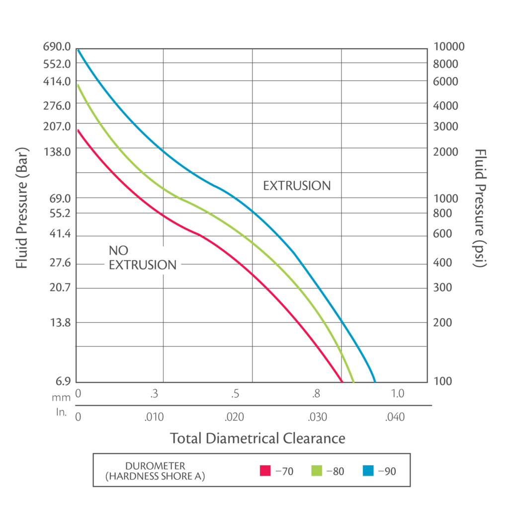
Extrusion Gap
Extrusion is a concern for radial seals where there is a gap between the piston and the bore for a piston type seal or between the rod and throat diameter for a rod type seal. It is not typically a concern for face type seals where the metal parts to be sealed are in contact line-to-line. The issue is that at higher pressures and especially for softer O-ring elastomers, the O-ring can be forced by the pressure into the small gap between the piston (or rod) and the bore (throat diameter). Unless the bore (throat diameter) and the piston (or rod) are ensured to remain concentric by the hardware, we have to assume that entire possible gap can shift to one side (see diagram below).
| Piston Type Seal Radial Extrusion Gap = (Bore Ø – Piston Ø)/2 | Rod Type Seal Radial Extrusion Gap = (Bore Ø – Rod Ø)/2 |
Ø = Diameter
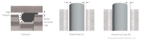
Limits for Extrusion
There are different methods to counter O-ring extrusion. One of these methods is to simply increase the durometer rating of the O-ring. However, as the durometer is increased, the O-ring can become less malleable. Another option would be to use anti extrusion devices. These are thin rings made of hard plastic materials such as KasPex™ PEEK, PTFE, and nylon. Once in place these rings will provide essentially zero clearance.
Reduce the clearance shown by 60% when using Silicone (VMQ) or Fluorosilicone (FVMQ) elastomers.