
Static Radial Applications
Information is based on ISO 3601
* Pneumatic applications typically do not use a Back-up ring.
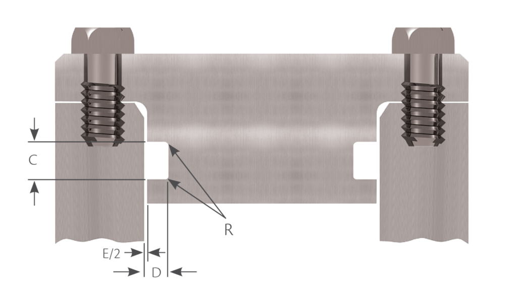
| O-Ring C/S | D | Squeeze | E | C | R | |||
|---|---|---|---|---|---|---|---|---|
| Groove Depth | Inches | % | Diametrical Clearance Max. | Groove Width +0.010/-0.000 | Groove Radius | |||
| No Back-Up Ring | One Back-Up Ring | Two Back-Up Rings | ||||||
| 0.070 | 0.049 -0.057 | 0.010 -0.025 | 14 -35 | 0.004 | 0.110 | 0.165 | 0.220 | 0.008 - 0.016 |
| 0.103 | 0.075 -0.087 | 0.013 -0.031 | 13 -30 | 0.005 | 0.150 | 0.205 | 0.260 | 0.008 - 0.016 |
| 0.139 | 0.101 - 0.117 | 0.018 - 0.042 | 13 - 30 | 0.006 | 0.197 | 0.252 | 0.307 | 0.016 - 0.031 |
| 0.210 | 0.156 - 0.180 | 0.025 - 0.059 | 12 - 28 | 0.006 | 0.283 | 0.354 | 0.429 | 0.016 - 0.031 |
| 0.275 | 0.212 - 0.242 | 0.028 - 0.069 | 10 - 25 | 0.007 | 0.374 | 0.484 | 0.594 | 0.031 - 0.047 |
Static Axial (Face) Applications
Internal Pressure: O-ring OD = Gland OD
External Pressure: O-ring ID = Gland ID
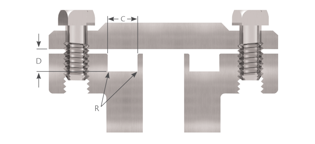
Information is based on ISO 3601.
| O-Ring C/S | D | Squeeze % | C | R | |
|---|---|---|---|---|---|
| Groove Depth +0.004/-0.000 | Groove Width +0.008/-0.000 | Groove Radius | |||
| Hydraulic | Pneumatic | ||||
| 0.070 | 0.051 | 21 - 36 | 0.126 | 0.114 | 0.008 - 0.016 |
| 0.103 | 0.079 | 19 - 30 | 0.157 | 0.142 | 0.008 - 0.016 |
| 0.139 | 0.106 | 17 - 26 | 0.209 | 0.189 | 0.016 - 0.031 |
| 0.210 | 0.165 | 15 - 23 | 0.299 | 0.276 | 0.016 - 0.031 |
| 0.275 | 0.224 | 13 - 20 | 0.354 | 0.335 | 0.031 - 0.047 |
Reciprocating Applications
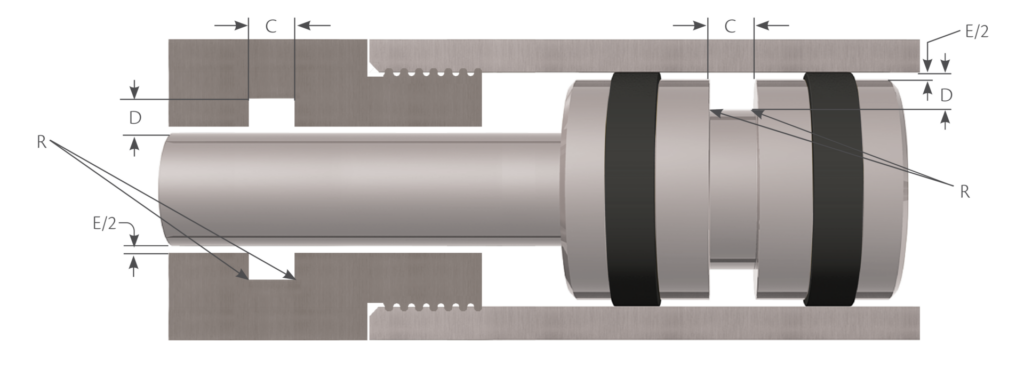
Information is based on ISO 3601
* Pneumatic applications typically do not use a back-up ring.
| O-Ring C/S | D | E | C Groove Width +0.010/-0.000 | R | |||||||
|---|---|---|---|---|---|---|---|---|---|---|---|
| Squeeze | Diametrical Clearance Max. | Groove Radius | |||||||||
| Groove depth | Hydraulic | Pneumatic | No Back-Up Ring | One Back-Up Ring | Two Back-Up Rings | ||||||
| Hydraulic | Pneumatic | Inches | % | Inches | % | ||||||
| 0.070 | 0.054-0.058 | 0.056- 0.060 | 0.009- 0.019 | 13-27 | 0.007- 0.017 | 10- 24 | 0.004 | 0.110 | 0.165 | 0.220 | 0.008- 0.016 |
| 0.103 | 0.081- 0.088 | 0.083- 0.092 | 0.012- 0.025 | 12-24 | 0.008- 0.023 | 8-22 | 0.005 | 0.150 | 0.205 | 0.260 | 0.008- 0.016 |
| 0.139 | 0.112- 0.120 | 0.115- 0.125 | 0.015- 0.031 | 11-22 | 0.010- 0.028 | 7-20 | 0.006 | 0.197 | 0.252 | 0.307 | 0.016- 0.031 |
| 0.210 | 0.173- 0.182 | 0.177- 0.190 | 0.023- 0.042 | 11-20 | 0.015- 0.038 | 7-18 | 0.006 | 0.283 | 0.354 | 0.429 | 0.016- 0.031 |
| 0.275 | 0.229- 0.244 | 0.234- 0.253 | 0.025- 0.052 | 9- 19 | 0.017- 0.047 | 6-17 | 0.007 | 0.374 | 0.484 | 0.594 | 0.031- 0.047 |
| For piston applications groove width (w) values do not apply for 001-003 and 400-424 series O-rings. |
| For rod applications groove width (w) values do not apply for 001-003, 028-050, 135-178, 232-284, 350-395, 400-424, and 430-475. |
| For rotary applications contact our engineering team at engineering@hitechseals.com |
Groove Details
Piston & Rod Applications
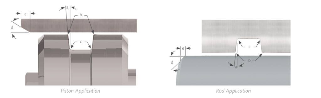
| Wall | Radius | Chamfer Length (e) | ||||||||
|---|---|---|---|---|---|---|---|---|---|---|
| O-Ring Series | O-Ring C/S | Angle | Break Edge | c | d at 15° | d at 20° | ||||
| Inch | mm | a | b | Inch | mm | Inch | mm | Inch | mm | |
| 000 | 0.070 | 1.78 | 0-5° | 0.004 - 0.012 Inch 0.10 - 0.30 mm | 0.008 - 0.016 | 0.20 - 0.40 | 0.043 | 1.10 | 0.035 | 0.90 |
| 100 | 0.103 | 2.62 | 0.008 - 0.016 | 0.20 - 0.40 | 0.059 | 1.50 | 0.043 | 1.10 | ||
| 200 | 0.139 | 3.53 | 0.016 - 0.031 | 0.40 - 0.80 | 0.071 | 1.80 | 0.055 | 1.40 | ||
| 300 | 0.210 | 5.33 | 0.016 - 0.031 | 0.40 - 0.80 | 0.106 | 2.70 | 0.083 | 2.10 | ||
| 400 | 0.275 | 6.99 | 0.031 - 0.047 | 0.80 - 1.20 | 0.142 | 3.60 | 0.110 | 2.80 | ||
Hardware Conditions
The metal hardware specifications of the O-ring gland and any mating part has a significant impact on the life and sealing performance of the O-ring. The following are general fluid sealing surface roughness values for glands using elastomeric O-Rings:
For a static mating surface: Ra 32 µinch maximum
For a dynamic mating surface: Ra 3-12 µinch
The recommended minimum shaft hardness is 50 HRC (Hardness Rockwell C).
For more detailed surface finish guidelines (gases, cryogenics, etc.), please contact info@hitechseals.com
O-Ring Tolerances (Non-Standard)
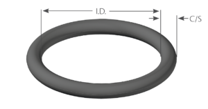
Information based on ISO 3601 Non-Standard Class A O-Rings.
| C/S | Tolerance |
|---|---|
| 0.80 < C/S ≤ 3.15 | ± 0.08 |
| 3.15 < C/S ≤ 4.50 | ± 0.10 |
| 4.50 < C/S ≤ 6.30 | ± 0.13 |
| 6.30 < C/S ≤ 8.40 | ± 0.15 |
| *9.00 ≤ C/S ≤ 20.00 | ± 0.20 |
*Based on DIN 3771.
Machining information and tolerances for various standards are available through Hi-Tech Seals.
Information provided in this catalogue is meant to aid with seal selection process.
Contact us for assistance in designing an application.
| I.D. (mm) | Tolerance | ||
|---|---|---|---|
| 0.68 | to | 1.53 | ± 0.10 |
| 1.54 | to | 11.69 | ± 0.13 |
| 11.70 | to | 13.46 | ± 0.15 |
| 13.47 | to | 17.53 | ± 0.18 |
| 17.54 | to | 20.57 | ± 0.20 |
| 20.58 | to | 23.88 | ± 0.23 |
| 23.89 | to | 28.70 | ± 0.25 |
| 28.71 | to | 35.56 | ± 0.30 |
| 35.57 | to | 43.18 | ± 0.36 |
| 43.19 | to | 50.80 | ± 0.41 |
| 50.81 | to | 58.42 | ± 0.46 |
| 58.43 | to | 66.55 | ± 0.51 |
| 66.56 | to | 74.93 | ± 0.56 |
| 74.94 | to | 83.57 | ± 0.61 |
| 83.58 | to | 92.20 | ± 0.66 |
| 92.21 | to | 101.60 | ± 0.71 |
| I.D. (mm) | Tolerance | ||
|---|---|---|---|
| 101.61 | to | 117.35 | ± 0.76 |
| 117.36 | to | 141.22 | ± 0.89 |
| 141.23 | to | 166.37 | ± 1.02 |
| 166.38 | to | 192.02 | ± 1.14 |
| 192.03 | to | 218.69 | ± 1.27 |
| 218.70 | to | 253.37 | ± 1.40 |
| 253.38 | to | 289.56 | ± 1.52 |
| 289.57 | to | 347.98 | ± 1.78 |
| 347.99 | to | 408.94 | ± 2.03 |
| 408.95 | to | 472.44 | ± 2.29 |
| 472.45 | to | 571.50 | ± 2.54 |
| 571.51 | to | 711.20 | ± 3.05 |
| 711.21 | to | 855.98 | ± 3.56 |
| 855.99 | to | 1005.84 | ± 4.06 |
| 1005.85 | to | 1163.32 | ± 4.57 |
| 1163.33 | to | 1320.80 | ± 5.08 |