 |
|
U-Cup Description
U-cups are a lip seal, named for the cross-section's distinctive "U" shape. They are used for both dynamic and static applications. The "U" shape energizes the sealing lips as the application pressure increases. This brilliant design has been modified to create several unique configurations. These modifications provide additional benefits for a variety of applications. The U-cups designs listed below are Hi-Tech Seals' most common designs.
| U-Cup Designs
|
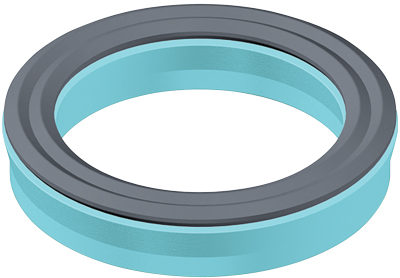
 | Loaded U-CupsLoaded U-cups were primarily designed for dynamic reciprocating applications. The O-rings loader makes this seal excellent for low-pressure rod and piston applications. With loaded U-cups as the system pressure increases, so does the force on the loading lips. Sealing force automatically compensates for the higher pressure, maintaining a positive seal. Loaded U-Cup Design
|
|
|
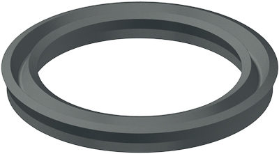
 | Unloaded Urethane U-CupsThe unloaded urethane U-cup design provides an excellent heavy-duty seal for both piston or rod applications and works well in static and dynamic applications. The unloaded urethane U-cup is commonly known as a Disogrin U-cup. Unloaded Urethane U-Cup Design |
|
|
 | Homogenous U-CupsHomogenous U-cups are popular in low-pressure applications where a low friction seal would be beneficial. They are most commonly used in pneumatic applications. Homogenous U-Cup Design |
|
|
 | DZ SealsDZ seals are squeeze type seals, primarily used for heavy-duty rod applications. DZ seals have excellent sealability, low compression set and superior anti-extrusion characteristics compared to other lip seals. Under low-pressure conditions, the sealing lip provides its own compressive sealing force. DZ Seal Design |
|
|
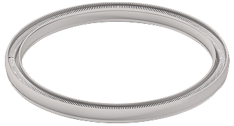 | Spring Energized Seals
Spring energized seals are engineered plastic seals that incorporate a metallic spring. The spring loads the seals lips against the mating hardware, creating a seal capable of compensating for movement in dynamic applications.
Spring Energized Seal Design |
|
U-Cup Selection Criteria
Hi-Tech Seals offers an extensive selection of U-cup designs. When selecting the proper U-cup for an application, many design elements and general guidelines must be considered. Using these criteria throughout the selection process will ensure the desired sealing requirements of the application will be met, i.e. resistance to wear and extrusion gap, resistance to high and low temperature, etc. Listed below are general guidelines and design elements to consider during the selection process.
Hi-Tech Seals recommends contacting a representative when designing a new application, to ease the selection process. The Seal Application Data Sheet assists with communicating the needs of an application with a Hi-Tech Seals' representative.
Eng.  | Fr. | Fr.
|
General Design Elements to Consider When Selecting a U-Cup:
|
1. Fluid Media - Chemical Compatiblity Look Up
|
The chemical compatibility guide offers the ability to view over
2000 chemical and their compatibility to a variety of materials. |
2. Service Materials
|
The minimum and maximum service temperature of a seal and fluids will further determine which material and seal type are suitable. |
|
| Material | Temperature | Advantages |
|---|
| Nitrile | -40°C/-40°F |
to |
120°C/248°F |
- Exceptional balance of good mechanical, wear resistance,
and reasonable resilience |
| Low Temp. Nitrile | -54°C/-65°F |
to |
116°C/241°F |
- Increased low temperature capabilities |
| Fluorocarbon | -26°C/-15°F |
to |
204°C/400°F |
- Resistant to high temperatures
- Wide range of chemical resistance
- Very good ozone, weather and aging resistance |
| Urethane | -54°C/-65OF |
to |
105°C/221°F |
- High tensile strength, toughness and wear resistance
- Good combination of hardness and elasticity |
| Hytrel® | -54°C/-65°F |
to |
149°C/300°F |
- Excellent strength and toughness properties |
| Ethylene Propylene | -54°C/-65°F |
to |
150°C/302°F |
- Excellent resistance to ozone, hot water, steam & aging |
| Hydrogenated Nitrile | -40OC/-40°F |
to |
160°C/320°F |
- Good extrusion, abrasion and wear resistance
- Improved chemical resistance |
| Chloroprene | -40°C/-40°F |
to |
121°C/250°F |
- Exceptional ozone and weather resistance
- Mechanical properties retained over a wide temp. range |
| Virgin PTFE | -268°C/-450°F |
to |
250°C/482°F |
- Virtually universal chemical resistance |
| 15% Glass filled PTFE | -268°C/-450°F |
to |
250°C/482°F |
- Increased compression and tensile strength
- Increased wear resistance
- Increased cold flow resistance |
| 40% Bronze filled PTFE | -268°C/-450°F |
to |
250°C/482°F |
- Increased hardness
- Decreased friction |
| 25% Carbon Graphite Filled PTFE |
-268°C/-450°F
|
to
|
250°C/482°F
|
- Increased hardness
- Increased wear resistance
- Decreased friction |
*The material information listed above is based on multiple references sources accept by industry. This information is Hi-Tech Seals Inc. accepted standards.
|
|
3. System Pressure
|
The ability of a seal material to withstand pressure varies depending on the compound. The figure below displays the maximum operating rating recommended for standard sealing compounds. The maximum pressure, and extrusion gap, will determine the risk of seal extrusion failure in an application. |
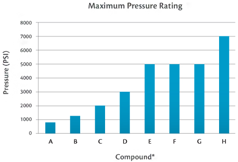 |
*A = 70 Durometer Nitrile, Fluorocarbon, Ethylene Propylene
B = 80 Durometer Nitrile, Fluorocarbon, Ethylene Propylene
C = 90 Durometer Nitrile, Fluorocarbon, Ethylene Propylene
D = Virgin PTFE
E = 15% Glass Filled PTFE
F = 40% Bronze Filled PTFE
G = Polyurethane
H = Hytrel
Note: The pressure ratings are based on a test temperature of 70°C/160°F. Tests were conducted without the use of a back up device and without reduced clearance gaps.
|
4. General Hardware Design Guidelines
|
For ease of assembly and to avoid damage to a seal during assembly, Hi-Tech Seals recommends that hardware follow the leading edge chamfers and dimensions guidelines shown below. |
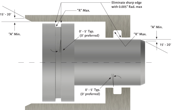 | |
Installation Chamfer,
Gland Radius & Taper |
|---|
Seal
C/S | �A�
Dimension | �R�
Dimension |
1/8 | 0.050 | 0.015 |
3/16 | 0.080 | 0.015 |
1/4 | 0.080 | 0.015 |
5/16 | 0.085 | 0.015 |
3/8 | 0.090 | 0.015 |
1/2 | 0.120 | 0.030 |
5/8 | 0.145 | 0.040 |
3/4 | 0.170 | 0.040 |
1 | 0.225 | 0.080 |
|
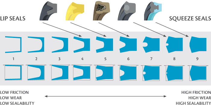
5. Leakage & Lip Squeeze
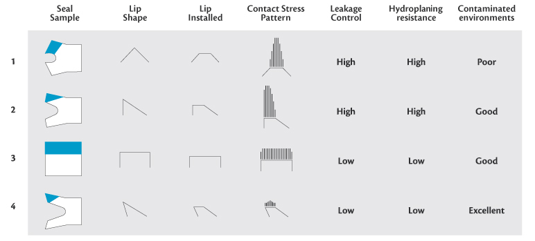
6. Performance Criteria
7. Retrofit and Gland Size
|
Many U-cup designs are built to fit existing gland designs. Much consideration should be taken to select the U-cup design that will fit the existing gland or the new gland specification. |
8. Installation
|
Some seal types are easily installed, while others are more difficult. Installation methods vary depending on a seal's profile, size, material, and the application where it is being installed.
Certain design factors need to be taken into consideration, as to protect the seal during installation. To learn more, contact a Hi-Tech Seals' representative.
|
9. Seal Life Expectancy
|
A seal's life expectancy varies depending on seal type and material. Its performance depends on several factors including duty cycle, stroke, speed, pressure, surface finish, and fluid type. Each material is assigned a specific PV (pressure/velocity) values to create a theoretical guideline. In general, products that last longer will have a greater cost. |
10. Price and Availability
|
The ideal U-cup will be a cost-effective solution for the end user. |
|
|